![]()
![]()
![]()
![]()
![]()
![]()
![]()
![]()
![]()
![]()
|
Join my Mailing List to keep up to date with my projects. Email Address:
|
The Magnetic or Small Wire Loop as
Designed and patented by Ben Edginton G0CWT.
Patent No GB 2285712
 I
first used this type of loop in 1985 but at that time it consisted of 64 foot of
wire hung from a mast with a spreading cane near the top and was fed with R.F.
using a single turn coupling coil at the top of the loop.
I
first used this type of loop in 1985 but at that time it consisted of 64 foot of
wire hung from a mast with a spreading cane near the top and was fed with R.F.
using a single turn coupling coil at the top of the loop.
It was tuned at the bottom of the mast with a conventional variable capacitor nothing to special I suppose .
It worked well for me for some time but I was always having to fiddle with the coupling coil and when the wind finally forced me to start again I decided to see if I could improve on it .
After some abortive attempts to use a form of gamma matching I decided to try a transformer to feed in the RF and also to match the loop to the 50ohm feeder.
My first attempts did not work I had taken information from the ARRL Antenna book which told me that the radiation resistance of the loop would be less than 0.1ohm on 80 metres and I took this to be the feed point resistance as it appears does every one else I have spoken to .
At 50 ohms to 0.1 the impedance ratio is 500 to 1 this means the square root of 500 = 22.36 so the transformer would have to be 22 to 1 . turns ratio.
I first located two ferrite tubes that I thought would be suitable and put them side by side and used two copper tubes to make the secondary 1 turn winding ,using two end plates made of copper clad board I then wound 22 turns of wire through the center to make the primary winding .
I now had my 500 to 1 impedance ratio transformer I connected it in series with the remotely controlled tuning capacitor and the 64 foot of wire loop that I had pulled up the 25 foot mast.
I went down to the transceiver and tried to tune up on 80 metres , no chance not even a hope checked everything and tried again no possible SWR reading .
I decided that the problem was the matching transformer but how to find out ,well I began to reduce the number of turns on the primary winding and found that when the turns where reduced the SWR began to show results but it was not until the primary was down to 2 turns that I could get anywhere near to a 1 to 1 swr.
I then realized that the feed-point resistance of the loop when fed next to the tuning capacitor was much higher than anyone realized.
It then took me some considerable time to pin it down exactly but the end results are that the feed-point resistance of a quarter wave loop next to the capacitor is 22.3 ohms and when it is fed at the point opposite to the capacitor the feed-point resistance is 5.5 ohms and there is a corresponding change around the Loop Circumference
Now I had the facts I could easily make up transformers for all feed points around the loop and the correct turns ratio when used with a 64 foot wire loop tuned up on 80 meters is just 1.5 to 1 when it is fed next to the capacitor as you will appreciate to get a 1.5 to 1 turns ratio I had to use three turns on the primary and 2 turns on the secondary instead of one turn ,this worked perfectly giving a 1 to 1 SWR on 80 metres
Now the second requirement of my loop was that it could be tuned up on 160 metres so to do this I had to find the feed point impedance on this band ,well to cut a long story short it turned out to be 2. 4 ohms at the feed-point next to the capacitor.
So to make the loop suitable for both bands I had to make a transformer with a primary of 9 turns taped at three turns and a secondary of 2 turns and switch it remotely by relays from 3 to 9 turns to change from 80 to 160 metres.
The end result was so good that I decided to apply for a patent and the filing date was 17-1-1994. I was finally granted patents in 1998.
Below is a sketch of the ferrite matching transformer and tuning capacitor as used with the small loop wire antenna for 80 and 160 metres.
The turns used to match the 64 foot of wire
to the 50 ohms coaxial feeder are a nine turn primary tapped at three turns and
a secondary
 of
two turns . The three turn primary tap is for 80 metres and the nine turns are
used for 160 metres
of
two turns . The three turn primary tap is for 80 metres and the nine turns are
used for 160 metres
It has been successfully used for D.X. at power up to the legal limit on both bands
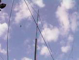
The picture below was taken at Long Leat and shows a mobile version of the magnetic or small wire loop that will work on 40, 80, and 160 metres using a modified transformer.
The matching and loading unit is situated in the roof of the R.V. the wire is only 32 foot long and is supported on a fiber glass pole which can be raised or lowered in less than two minuets.
A similar arrangement can be used on a small boat or static caravan and can easily out perform all whip antennas.
--------------------------------------
Email ben@edginton.info [c] B.Edginton.2001