|


|
Join my Mailing List to keep up to date with my
projects.
Email Address:
|
| |
Wide Band Tuned Loop
|
7.5 ohms Resistance loop
|
Copper Wire Loop |
|
Wide band tuned
loop? That sounds like a contradiction of terms and for many
years the experts have told us that magnetic or tuned loops have
an extremely low radiation resistance of around 0.01 ohms. Next
they say the current is uniform around the loop and so we must
use large diameter tubing to stop most of the RF being lost in
resistance, heat and skin effects. And finally that the loop is
very inefficient.
Well I don’t agree with them,
and I will now tell you why.
Ever since I first used a ferrite transformer to successfully
couple a ¼ wave wire loop to a transceiver I have known that the
input impedance of a quarter wave loop must be about 22.2 ohms
when fed next to the tuning capacitor.
It had to be because the only transformer ratio that would give
an SWR of 1 to 1 used a 1.5 to 1 turns ratio and that means 50
ohms down to 22.2 ohms. This can easily be confirmed.
This means that because of the relatively high impedance at this
feed point losses from dc resistance in the loop are at a
minimum and thick tubing is not necessary.
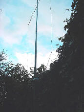
In order to prove this I have made a 32 foot ¼ wave loop for 40
meters and deliberately used a wire that is normally used for
soil warming and has a total DC resistance of 7.5 ohms.
This 32 foot of resistance wire was pulled up into position as a
loop (see picture number 1) and I found that it would tune on
7.0 MHz but that the SWR was very high this turned out to be
because the 1.5 to 1 turns ratio of the transformer was now
looking at a total resistance of 22.2 ohms plus 7.5 ohms = 29.7
ohms.
At first I settled for a 1 to 1 transformer and found that it
gave me a 1.4 to 1 SWR this allowed the transceiver to put out
50 watts without the ALC shutting it down.
.
The receive was very good with no noticeable loss, so now I
needed to test the transmit capability.
To do this I used my computer to connect me to a DX Tuner on the
Internet.
This allowed me to monitor my signal from a distance (I did not
want to involve other Amateurs at this stage of the game)
The Atlantic DX receiver at Ilfracombe was not being used so I
switched on the transceiver and put out a test signal.
I was delighted to hear the tone being received in Ilfracombe
and returned to me via the Internet.
This proved to me that my lossy loop was actualy radiating a
great deal of the 50 watts that I was putting into it.
Now I needed to check it against a loop that was made with
copper wire of low resistance.
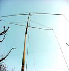
I set up this second 32 foot wire loop as far away from the
resistance wire loop as I could by hanging it inside the 64 foot
80 meter loop. see picture number 2. I then tuned both 32 foot
loops to 7.050 MHz.
Now I could alternate my transmissions between the copper wire
loop and the resistance wire loop and listen to my own
transmissions on DX tuners when they were not being used by
short wave listeners.
Surprisingly there was almost no discernable difference in the
signal strength that the remote tuners were receiving.
A few more experiments and a few days later I thought it was
time to see how it performed in a live contact test. I tuned
both loops to 7.05 MHz and listened around finally a station
ON3CYN came up just below and I tuned up and gave him a call on
the resistance wire loop.
He came right back and gave me a report of 5 by 8 to 9 and told
me he was activating a Windmill number 2925 in Belgium. We
talked for some minutes and I left him to call in a few of the
others that were calling him. Things had gone so well I
completely forgot to try him with the good copper wire loop.
My next opportunity to call a notable station was IO2MET
Antarctica special event at 5-15 on the 21-2-2006 on 7.045 MHz I
was still using the 7.5 ohm resistance loop and about 75 watts,
he gave me the traditional 5-9 and said I was in the log and
that his QSL manager was IK2IWU he then went back to others who
were calling him.
|
|
|
These experiments have
confirmed my prediction that the 7.5 ohms resistance is almost certainly
only losing about 25% of the power that is fed into the ¼ wave loop. But
if the loop resistance had been 0.01 ohm as predicted by the anti loop
brigade then 750 parts of the power would have been wasted as heat in
the resistance wire. leaving only about 0.1 of a watt to be radiated.
|
|
I think the results of my
test show that at least 50 % of the RF was doing something other than
just warming up the resistance wire.
Now I come to an important spin off from this experiment. When tuning I
found that although the SWR was 1.4 to 1 it did not change very much
when tuning away from the resonant frequency and a band width of 200 Kcs
tuning from 7.0 MHz to 7.195. MHz with the SWR staying inside 1.7 to 1
and almost 500 Kcs band width when staying just inside an SWR 2 to 1.
Across the 7 MHz band the receive sensitivity hardly changed and it was
also still possible to transmit without re-tuning the loop although more
power must have been lost.
It still bothered me that I had not got a good match at the feed-point
so I did a little calculation and found that to match the 22.2 plus 7.5
ohms say 30 ohms to the 50 ohms of the transceiver I would have to use a
5 to 4 turns ratio transformer.
I did not want to alter anything to much so I left the 2 turn secondary
in place and put 2½ turns on the primary by passing the wire through one
ferrite an extra time.
This I found bought my SWR down to, 1 to 1 and the bandwidth was about
the same as before, Showing once again that by using 22.2ohms as the
loop feed point impedance in my calculations for a ¼ wave tuned loop
things work out fine.
I think that the resistance wire loop could have some advantages once we
accept that maximum power is not always the main criteria and that a
high bandwidth could out-way the loss of RF that will be present in this
type of loop.
Copyright 2006 © B Edginton G0CWT |
|
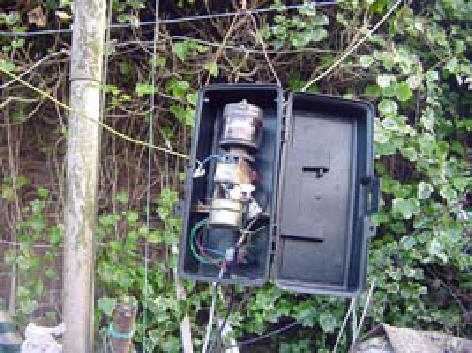
Loop Tuner in Box |
|