![]()
![]()
![]()
![]()
![]()
![]()
![]()
![]()
![]()
![]()
|
Join my Mailing List to keep up to date with my projects. Email Address:
|
There Are Now Eight Ways to Feed a Magnetic or Small Loop.
The drawing of seven loop arrangements was published in RadCom in 1986 and is
reproduced with the permission of the RSGB".
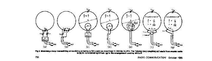
At that time it was thought that there where only seven ways to feed R.F to a magnetic or small loop. The first two (a) and (b) are fed using capacitors and are difficult to tune. The other five are not suitable for use with a wire loop.
On the 17-04-1994 Patents were filed by Edginton on a new type of loop, this new loop is fed with RF from a transformer.

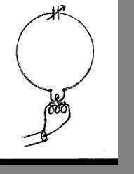 The
drawing to the right shows this system using a ferrite transformer.
The
drawing to the right shows this system using a ferrite transformer.
So now there are eight ways to feed RF into a loop antenna.
In practice the capacitor can be placed next to the transformer which is the highest input impedance point on the loop.
The Edginton Loop has the advantage that it is a more efficient and flexible arrangement allowing the loop to be fed at any point around its circumference providing the transformer ratio is designed for that feed point.
When the transformer is placed next to the capacitor it resembles an end fed wire that is voltage fed and if fed at the point opposite to the capacitor it then resembles a center fed antenna and is current fed at the lowest impedance point.
This loop arrangement made it possible to investigate more thoroughly the the current and voltage distribution around a small loop antenna.
Animated gif Showing the Radiation Lobes of the Small Loop
By Ben Edginton G0CWT. (C) copyright. 2000. Please wait for animation to start.
In this Animation the Small loop antenna is
represented by the oscillating circle, the blue indicates the alternating
voltage across the capacitor that changes
polarity at each cycle.
The current in the loop is concentrated mainly around the part of the loop that is furthest from the capacitor and is indicated by the red infill behind the loop.
I have not included the coupling transformer in this animation but it can be place at any point around the loop without altering the voltage and current pattern ,only the input impedance will change. This is explained on other pages of this web site.
The animation demonstrates the general direction of the maximum radiation, away from the loop when the capacitor is at the bottom of the loop.
There are other small complex lobes present but in practice they are not of any great importance to the Radio Amateur.
In trying to understand the behaviour of the Small loop it helps to look upon it as a resonant dipole that is bent into a circle. The tuning Capacitor is to compensate for the shorter length of the element.
The second Animation is that of a Ground-Plane Vertical Antenna .
Blue is again used to indicate the voltage
field which is highest at the tip of the antenna.
As the voltage drops to zero it leaves a Traveling Electric field that is then pushed outwards and away from the antenna as the voltage rises again in the opposite polarity.
When the current collapses it leaves a horizontal circulating magnetic flux ring which is pushed outwards by the next input of current this creates a Travelling Magnetic field, represented by the red rings.
It is the vertical electric field combining with the horizontal magnetic field in a hatch like manner at right angles to each other that launch the electro-magnetic radiation waves into space.
The animations are an attempt to illustrate how the Small Loop and the Ground Plane antenna emit the electromagnetic waves.
I would like to hear from you if you have any constructive comments to make.